Have you seen a motor? Surely, we all have seen and used motors, from the mobile phone in our pocket to huge industries. We use motors at home and in industries.
For example, at home, we use motors in the form of mixers, juicers, refrigerators, water pumps, fans, vacuum cleaners, and washing machines. Computer hard disks, CDs, DVD players, and the vibration mode of our cell phones also use motors. In the industries, the various operations are done by motors. Let us see the different types of motors, their principle of working, and their applications.
What is an Electric Motor?
An electric motor is a machine that uses electrical energy and converts it to mechanical energy, in the form of rotation.
The Principle Behind the Working of Electric Motor
When electric current passes through a conductor, it creates a magnetic field around it. This field exerts a force on a magnet kept nearby, making it move. This was first observed by Hans Christian Oersted in 1820.
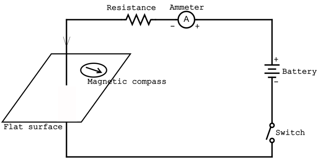
In this figure, a circuit is set up consisting of a battery, ammeter, resistance, and switch. A long, straight conductor passes perpendicularly through a flat surface such as cardboard. A magnetic compass is kept on the surface. When the switch is closed, current flows through the circuit making the compass needle deflect. This shows that a force is created by the current that makes the magnetic needle deflect.
Ampere's Discovery
A French scientist named Andre Marie Ampere suggested that the reverse might also be true, that is, the conductor carrying some current must also experience a force when placed inside a magnetic field. He experimented and showed that the current-carrying conductor moves when it is placed inside a magnetic field.
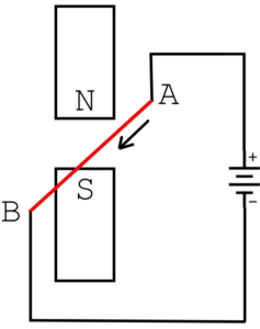
This figure shows the simplified setup of Ampere’s experiment. The conductor AB, marked in red, is a straight rod and is suspended freely between the two poles of a magnet. When current is passed through the conductor, it is observed that the suspended conductor moves left or right, depending on the direction of the current through it.
This is called the “Magnetic effect of electric current”. This mutual effect of current and magnetic field on each other is the basis for the working of motors, generators, microphones, loudspeakers, magnetic tapes, computer hard disks, and measuring instruments.
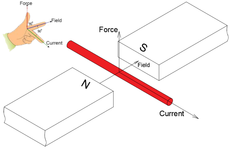
It has been proved that the magnitude of force experienced is highest when the directions of the current and magnetic field are at right angles to each other. In such a scenario, the direction of movement of the conductor is perpendicular to both of them.
Fleming's Left Hand Rule
As written above, the direction of the current, the direction of magnetic field, and the direction of movement of the conductor are perpendicular to each other, similar to the edges of a cube. The direction of movement of the conductor due to the flow of current through a conductor in a magnetic field can be found by Fleming’s left-hand rule.
Hold the left hand such that the thumb, forefinger, and middle finger are at right angles to each other.
The forefinger represents the direction of the magnetic field from north to south.
The middle finger points in the direction of the current.
The thumb represents the direction of movement of the conductor due to the force.
Working of the Electric Motor
To understand the working of a DC motor, let us study a simple motor with a single coil.
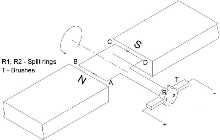
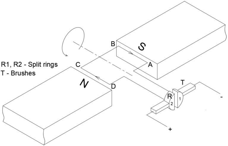
This motor consists of a single coil in the shape of a rectangle. It is placed between two poles of a magnet such that the sides of the coil are perpendicular to the magnetic lines from north to south. The ends of the coil are connected to two semi-circular rings. They are called split rings (R1 and R2 in the figure). Each split ring has a block made of graphite or copper pressing against it. They are called brushes (T in the figure). They are made to press tightly against the split rings using springs. Direct current is supplied to the motor by connecting wires to the brushes.
Initially, let us assume that side AB is near the north pole, and side CD is near the south pole.
a. When the switch is turned on, current flows from the positive of the battery to the coil through the left brush and split ring R1, and returns to the negative through R2 and the right brush.
b. Current flows from A to B, and from C to D. The conductor experiences a force causing it to move. From Fleming’s left-hand rule, we can see that the direction of movement of side AB is downwards.
c. Similarly, in the side CD, the direction of movement is upwards. Since both sides of the coil move in the opposite direction, the entire coil rotates in the anti-clockwise direction.
d. After half rotation, the side CD is near the north pole and side AB is near the south pole. Note that the split rings also rotate along with the coils. Due to the split rings, the direction of the current inside the coil does not change. Therefore, the current now flows from D to C, and from B to A.
e. The direction of force experienced by both sides is still the same and the coil rotates in the anti-clockwise direction. For every half turn, the direction of the current reverses inside the coil, making the entire coil rotate only in one direction. This continues and the coil rotates continuously.
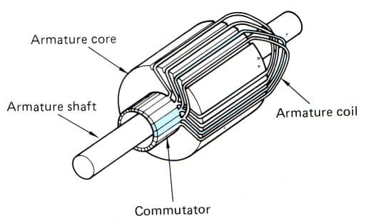
f. In a regular motor, there are many coils, called the armature. The coils of the armature are wound over a core made of magnetic material. Each end of a coil is connected to a split ring. The set of split rings is called the commutator.
Parts of an Electric Motor
In a regular motor, there are many coils, called the armature. The coils of the armature are wound over a core made of magnetic material. Each end of a coil is connected to a split ring. The set of split rings is called the commutator.
Motors can be DC motors and AC motors depending on the type of supply.
Rotor and Stator are the two major parts of any type of motor.
Rotor: It is the rotating part of the motor. In the figures used, the coil is part of the rotor.
Stator: It is the stationary part of the motor. In the figures used, the magnetic poles are part of the stator.
In an actual motor, there are more than two poles. Large motors have electromagnets instead of permanent magnets.
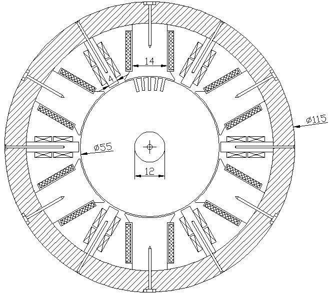
The motor considered in this article is a DC motor. In this motor, there are 6 main poles, indicated by the wide rectangles. The thin poles between them are called interpoles, and they are part of the main poles. The main poles and the interpoles are attached using bolts to a circular disk called the yoke. The circle below the poles is the armature. The armature consists of slots to hold the conductors. The commutator is placed on the shaft, which is indicated by the smaller circle near the centre.
All the magnetic poles are electromagnets that are magnetized by coils wound around them as shown by the hashed rectangles in this figure. The poles and the armature conductors are supplied current from the same source.
Types of DC Motors and their Applications
As written above, motors can be DC or AC motors. While AC motors are used more commonly in homes and industries due to their many advantages, DC motors are also used in many applications. Some types of DC motors and their applications are:
Permanent magnet motors
These are small motors of low capacity. They are used in toys, computer drives, cell phone vibrators, portable drills, car wipers, etc.
Series motors
The magnetic field winding and the armature winding are in series. Series motors are used in lifts, cranes, hoists, and other heavy lifting applications.
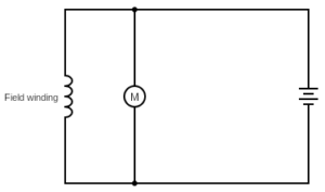
Shunt motors
In shunt motors, the field winding is in parallel with the armature winding. These motors are used in applications that need constant speed, and good speed control. Machines such as lathes, drilling machines, and fans use shunt motors.
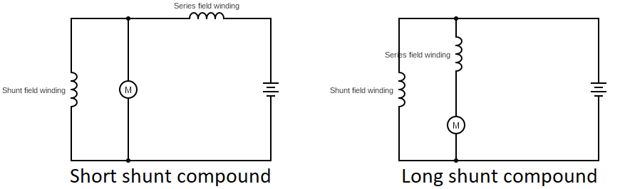
Compound motors
They are a combination of series and shunt motors. Based on the type of connection, they are classified as short shunt and long shunt compound motors.
Compound motors are used in conveyors, rolling mills, and elevators.
This is a simple article about DC motors. AC motors are more extensively used because of their various advantages compared to DC motors. We will talk about AC motors in another article.
Thanks for your personal marvelous posting! I quite enjoyed reading it, you are a great author. I will make sure to bookmark your blog and will eventually come back in the future. I want to encourage you continue your great posts, have a nice morning!


Woow, wanted this article. Thank a ton, dude
Thanks for your personal marvelous posting! I quite enjoyed reading it, you are a great author. I will make sure to bookmark your blog and will eventually come back in the future. I want to encourage you continue your great posts, have a nice morning!